Connect an external LED to a pin and make it turn on and off.
C Interface
#include "pico/stdlib.h"

// Initialise a pin to be used for GPIO.
//   - gpio is the GPIO number, not the Pin number.
void gpio_init(uint gpio);
// Set whether a GPIO is an input or an output.
//   - There are GPIO_IN and GPIO_OUT macros defined.
void gpio_set_dir(uint gpio, bool out);
// Put a digital value onto a GPIO.
void gpio_put(uint gpio, bool value);

// Wait for a number of milliseconds.
void sleep_ms(uint32_t ms);
Circuit
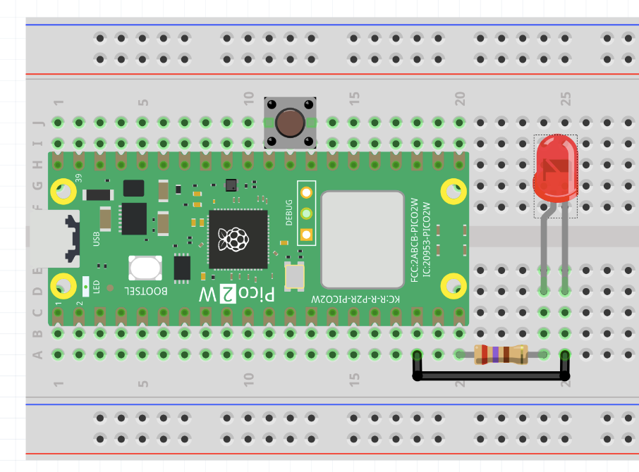
- 1x LED
- 1x Resistor (270 Ohm)
Connect the +ve terminal of the LED (has a longer leg) to GP15 (Pin 20), and the -ve terminal to GND. Make sure you place the resistor in series with the LED.
Python Instructions
Run the blink-led.py program and watch the LED flash on and off.
C instructions
Compile and upload the blink-led program from the workshop repository to see the LED flash on and off.
Explanation
We can’t connect the LED directly between a pin on the Pico and ground, there would be nothing to limit the current and so the LED would burn out.
We need to introduce a current-limiting resistor to make sure that the current through the LED stays at a safe level.
We can model the circuit using the following schematic:
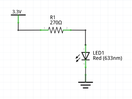
The LED has a forwards voltage drop of around 2 V, and can tolerate a maximum safe current of around 20 mA.
- In this case we don’t want to drive it at the maximum, so we choose a current of 5 mA.
- When the LED is turned on, it is modelled as an ideal voltage source.
Apply KVL around the loop:
Use Ohm’s law to find the resistance:
We normalise this to an E12 series value and get for the resistance.
Activities
Exercise
Can you connect a second LED and make it flash as well?
Try making it blink with a different frequency to the first one.
Exercise
Try and make the LED spell out a message in Morse Code