Components:
Python Interface
C Interface
// Set GPIO to be pulled up.
void gpio_pull_up(uint gpio)

// Set GPIO to be pulled down.
void gpio_pull_down(uint gpio)
Circuit
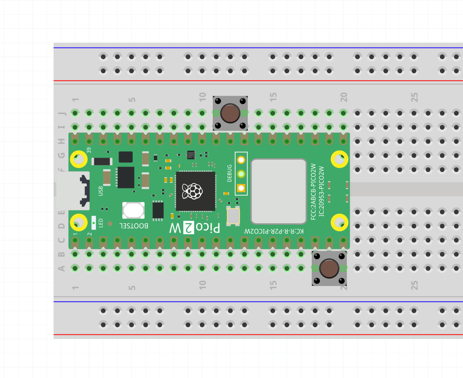
- 1x Momentary switch (Can re-use the reset button)
Connect the button between pin 20 (GP15) and the ground pin to the left.
Python Instructions
Run the code in button-input.py. Pushing the button turns on the builtin LED.
C Instructions
Look at the code in button-input.cpp, and upload it to the Pico.
When you push the button, the builtin LED turns on. It turns off when you release the button.
Info
In digital logic, a pin can be in two states: High (3.3V) and Low (0V). An output pin strongly drives the pin to one of these two states by connecting it to either Vcc or Ground.
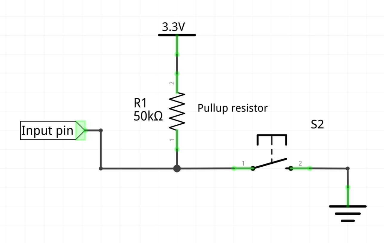
But an input pin is driven by the outside world, so the Pico puts it into a secret third state called High impedance (aka floating, High-Z). This state is neither High or Low, but an undefined state in between, the pin needs to be controlled externally to a High or Low value.
If a pin is left floating and we try to read a value, the result is undefined; it depends on various capacitances and noise that will affect the value you try to read. For this reason we use a large resistance to “pull” the pin voltage up or down to a High or Low state. The large resistance means the pull is weak and will be overridden by the input value we want to read. Imagine a pullup/pulldown resistor as a weak spring that stops the pin from floating between High and Low.
We could use an external resistor as a pullup, but the Raspberry Pi developers have thought of this already and included internal pullups and pulldowns that we can activate from code.
- The internal pullups on the Pico are around .
Exercises
Exercise
Can you make the button control an external LED on the breadboard?
How about making the LED blink on and off, but only when the button is pressed?
Exercise
Can you make the button toggle the LED?
- When you push and release the button, the LED stays on.
- When you push and release again, the LED turns off.
Hint: you will need to record some state in a variable.