Using the ADXL345 accelerometer module to measure acceleration.
Circuit
- 1x ADXL345 module Datasheet
Connect VCC and GND to the corresponding pins on the Pico. Connect SDA to GP04 and SCL to GP05. This will connect the ADXL345 in I2C mode.
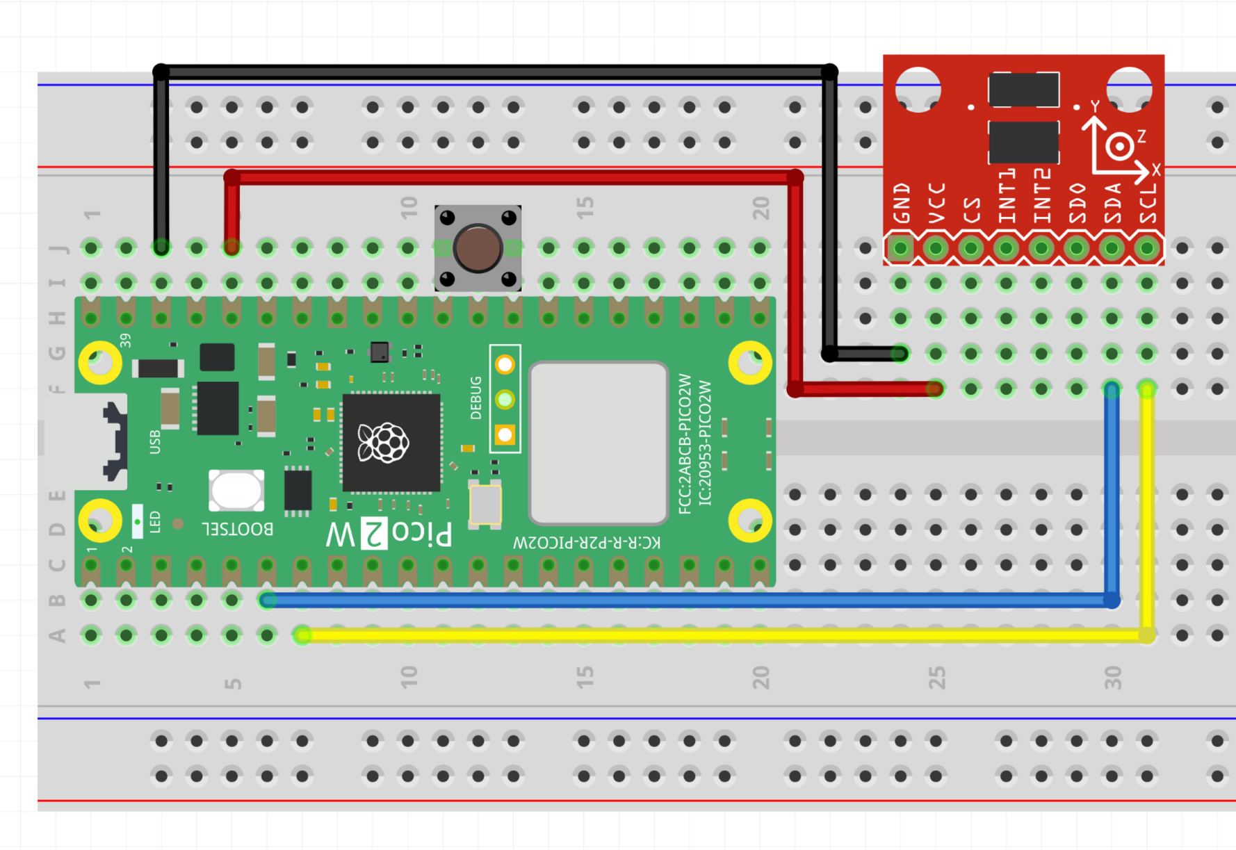
Look at accelerometer.cpp and load it onto the Pico. Watch the serial console to get the acceleration in the three axes. Try moving the board around and watch how the value changes. There is a marking on the ADXL345 module that tells which direction is X, Y and Z.
Info
The ADXL345 accelerometer uses MEMS technology, meaning there are microscopic mechanical devices inside the chip that move in order to determine the acceleration.
The ADXL345 module can operate using either SPI or I2C. In this example we are using I2C, but SPI would enable a faster sample rate.
Exercises
Exercise
Use an output component to indicate when the magnitude of the acceleration passes a certain value.
Hint: calculate magnitude using the Pythagorean theorem and the three axis components.
Exercise
Use PWM and the RGB LED to make each of the acceleration axes control the brightness of one of the colours of the LED.