Use Pulse Width Modulation (PWM) to create an analog output using a digital pin.
Components
- 1x RGB LED (Common cathode)
- 1x 270R Resistor
- 1x 1k Resistor
- 1x 1.5k Resistor
For the Piezoelectric Buzzer:
- 1x Piezoelectric Buzzer
C Interface
// Set a GPIO to PWM mode.
void gpio_set_function(uint gpio, gpio_function_t fn);

// Get the PWM slice that controls a GPIO
uint pwm_gpio_to_slice_num(uint gpio);

// Set the wrapping value for a GPIO slice
void pwm_set_wrap(uint slice_num, uint16_t wrap);

// Enable/disable PWM slice
void pwm_set_enabled(uint slice_num, bool enabled);

// Set the PWM level for a GPIO
void pwm_set_gpio_level(uint gpio, uint16_t level);
Instructions
RGB LED
The RGB LED has 4 pins. It has three LEDs inside: red, green and blue. It is in a common-cathode configuration, so one pin is connected to the cathode (negative side) of the three LEDs, and the other three pins go to each of the anodes (positive side).
Use the lengths of the pins to work out which one is which.
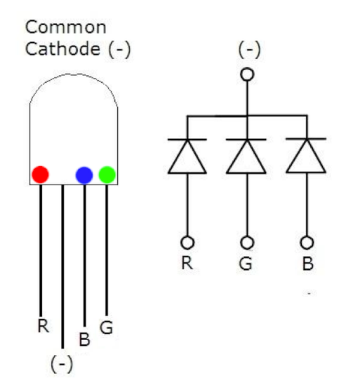
The longest leg is the cathode, and we need to connect it to ground.
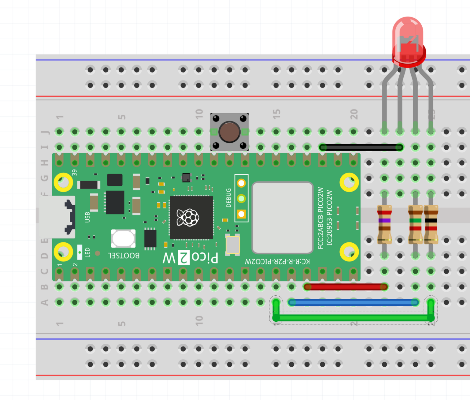 Make the following connections:
- Cathode to a
GNDpin - Red pin through a resistor to pin 17 (
GP13) - Blue pin through a resistor to pin 16 (
GP12) - Green pin through a resistor to pin 15 (
GP11)
Look at and run the code in pwm-rgb-led.cpp. You should see the red component of the LED smoothly pulse on and off.
Piezoelectric Buzzer
The Pico can generate PWM signals at audible frequencies. This means we can play sounds using PWM! A Piezoelectric buzzer can make noise using a crystal inside that changes shape when a voltage is applied.
Connect the buzzer between pin 20 (GP15) and GND. The buzzer has a polarity, so connect the (-) to GND and the (+) to GP15.
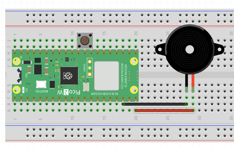
Check out pwm-piezo.cpp and run it on the Pico. The buzzer will play some alternating tones.
Info
Pulse Width Modulation (PWM) is a method of approximating an analog value using a digital output. The basic principle is that a high-frequency square wave signal is generated, where the average of the signal is the analog value that we want.
The exact analog value is controlled by varying the duty cycle, which is the fraction of time that the PWM is High vs Low.
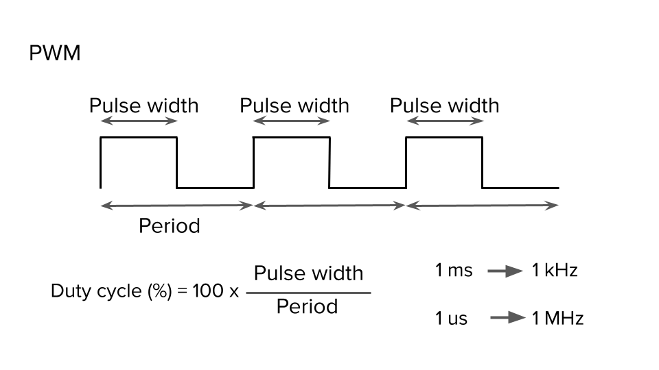
The Pico implements PWM using a number of “slices”, which control the GPIOs. Each slice has a counter that counts up until it reaches the wrap value, before starting again at 0. If the counter is less than the level, the output is High, otherwise the output is Low. So we control the duty cycle and frequency by varying wrap and level.
Playing Music
You can play musical tones by calculating the correct wrap value to use for a given frequency. You can look up the corresponding frequencies for notes on Wikipedia
Use the following formula to convert frequency to wrap:
- in our case.
Exercises
Exercise
Add code to make the green and blue components of the RGB LED pulse too.
Can you make them pulse at different speeds?
Hint: start by copying the code for the red pin.
Exercise
Edit your LED code to make it cycle through a rainbow pattern (red, orange, yellow, blue, green, purple, …)
Hint: how do you convert HSL to RGB? For a simple rainbow, saturation and lightness can be constant.
Exercise
Can you make the piezoelectric buzzer play a song?
Hint: use the
pwm_set_wrapandsleep_msfunctions to play the correct frequencies at the correct time.