Reading analog inputs with the Analog to Digital Converter (ADC).
Components
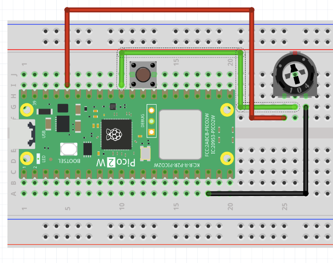
- 1x potentiometer.
C Interface
// Initialise the adc subsystem.
void adc_init();

// Initialise a GPIO as an ADC input.
void adc_gpio_init(uint gpio);

// Choose which GPIO goes to the ADC.
void adc_select_input(uint input);

// Read the value of the ADC. Value ranges from 0 to 4095.
uint16_t adc_read();
Instructions
The Pico 2 W has a single ADC that can take input from one of three pins: GP26, GP27, GP28. Refer to the diagram in pico-info for further details.
Potentiometer
Connect the left and right pins to 3.3V and GND, and the middle pin to GP26.
Look at and run adc-potentiometer.cpp, then connect to the serial port to monitor the value of the ADC.
Builtin Temperature Sensor
Run adc-temperaure.cpp to see the current temperature of the Pico get printed out over the serial console.
Explanation
There’s only a single ADC on the Pico, but it can choose an input from a few different sources, so you can monitor multiple analog values by swapping between them.
The ADC has 12 bits of precision, so there are possible values it can measure.
Exercises
Exercise
Create a dimmable LED. Use the ADC to control the PWM output of an LED.
Hint: refer to 2.3 PWM
Exercise
Use the ADC to control the pitch of the tone on a piezo buzzer.